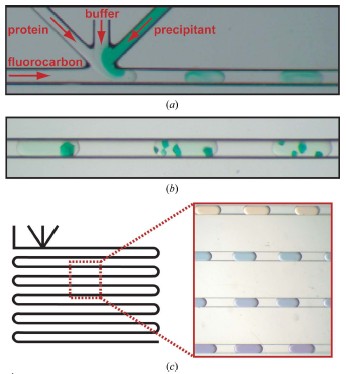
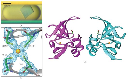
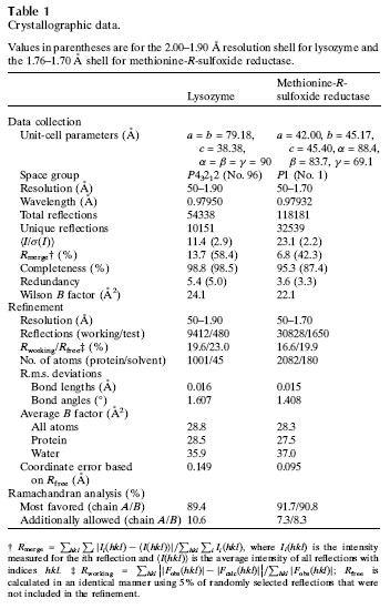
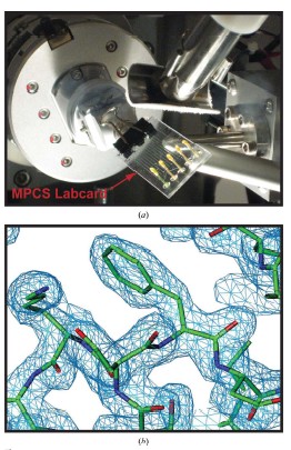
Cory J. Gerdts, Mark Elliott, Scott Lovell, Mark B. Mixon, Alberto J. Napuli, Bart L. Staker, Peter Nollert and Lance Stewart MPCS is a new semi-automatic droplet-based crystallization technology that allows screening of nanoliter volumes of crystallization conditions in plastic vessels, and crystals are readily harvested for use in traditional cryopreservation and X-ray diffraction data collection. Protein crystals grown in such plastic vessels can be directly subjected to downstream in situ x-ray diffraction analysis studies. MPCS is able to integrate the crystallization mixture for crystallization experiments. Approximately 10-20 nL of droplets are produced on a microfluidic Teflon tube or a plastic CrystalCard, each representing a batch of crystallization experiments with practically different chemical components. All protein samples were used in the crystallization experiment. Sparse matrix screening and chemical gradient screening are used in combination in a complete hybrid ('hybrid') crystallization experiment. This technique facilitates the use of high particle size gradient screening optimizations using optimized reagents such as precipitants, complexes or cryoprotectants. introduction Every year, the field of structural biology produces new technologies that increase throughput and efficiency. The initial goal of such development was to take three days from the gene to the three-dimensional structure. In order to increase efficiency, one may wish to minimize the amount of protein required so that sufficient material can be obtained from cell-free synthetic species for crystallization screening and optimization. Because of the goal of the 'three-day' structure, ATCG3D is committed to developing multiple technologies to increase gene-to-structure efficiency, including synthetic gene design (Gene Composer; http://), protein crystal imaging ( DETECT-X; Emerald BioSystems) 2. Background The microfluidic crystallization technology discussed here is developed at the University of Chicago (ATCG3D-Ismagilov Cooperative Lab). Aqueous solutions, referred to herein as plugs, in the form of a combination of micro-aqueous, spontaneous outflows are incompatible with biologically inert fluorocarbon solutions (Song et al., 2003; Tice et al., 2003, 2004). Protein, buffer and precipitant flow simultaneously through three separate single channels, where the flow of the insoluble and bio-inert fluorocarbons is controlled to break the formation of 10-20 nL of micro-dispensing crystals in the aqueous phase (Fig. 1a; Zheng et al., 2003; Zheng, Tice, Roach et al., 2004). The water flow in this area is called '3+1 mixer'. 10-20 nL of crystal droplets were formed in '3+1 mixer' while crystallizing and detecting (Fig. 1b). By controlling the flow, a series of well-concentrated droplets are produced (Fig. 1c), allowing the detector to carefully detect the crystalline phase space for crystal optimization. Droplet-based crystals allow for the use of pre-formed droplets for sparse matrix screening (Zheng & Ismagilov, 2005; Zheng, Tice & Ismagilov, 2004), by droplet formation and combined sparse matrix and gradient screening on the chip called 'hybrid The method' (Li et al., 2006) forms a suitable concentration gradient (Zheng et al., 2003). In the latter, the crystal phase space can be comprehensively screened in a single crystallization experiment. Droplet-based microfluidic crystallization is also used to explore the crystallographic nucleation of protein crystals (Chen et al., 2005; Zheng et al., 2005; Gerdts et al., 2006) and the scientific problems of crystallization of new protein structures ( Erdts et al., 2006). Figure 1: Droplet-based protein crystallization using MPCS. (a) Droplets formed on a CrystalCard in a crystallization experiment. (b) Crystals colored on the MPCS CrystalCard. (c) pH gradient (right) formed on the CrystalCard channel (left) using low-pH buffer, high-pH buffer and universal pH buffer indicator. 3.MPCS As a technology development center, ATCG3D developed the Microtubule Protein Crystallization System (MPCS) to develop a droplet-based protein crystallization technology for scientific research. This MPCS instrument consists of three main components (Figure 2): (1) a pump system, (2) MicroPlugger software and (3) CrystalCard. The pump system is a four-channel syringe pump system that provides precise and continuous flow into the MPCS CrystalCard. The system can control each channel independently and produce an excellent gradient. The pump is controlled by MicroPlugger software (Figure 2b). The MicroPlugger software allows the operator to control the pump system in four different modes of operation: Prime Mode (for priming the lines), Constant Mode (for constant-flow experiments), Gradient Mode (for generation of fine gradients) and Hybrid Mode (for sparse) -matrix screening using the hybrid method). These modes of operation are applicable to all MPCS experiments. The third important component is CrystalCard (Figs. 2c and 2d), which is a microfluidic chip where water and fluorine solutions spontaneously form 10-20 nL droplets in a 3+1 mixer. The CrystalCard design is a hydrophobic surface used to form droplets and has a long microfluidic capillary storage and inspection. The crystals used for diffraction can be physically extracted from CrystalCard or subjected to in situ X-ray diffraction. There are two forms of MPCS CrystalCard: one is plastic CrystalCard and the other is PDMS / Teflon CrystalCard. Plastic CrystalCard (Fig. 2c) is mainly used for fine-gradient screening, PDMS/Teflon CrystalCard (Fig. 2d) is mainly used for hybrid screening and detergent-based membrane protein forms (PDMS / Teflon CrystalCard necessary connection form) And surface properties are compatible with hybrid screening and detergent-based crystallization). Figure 2: MPCS composition. (a) MPCS system composition diagram. (b) Screenshot of the MicroPlugger software operating mode. (c) MPCS CrystalCard filled with pigmented protein crystals. (d) PDMS/polytetrafluoroethylene CrystalCard was used in the hybrid method. Using pump systems, software, and CrystalCards, MPCS produces hundreds of different MPCS crystals in minutes, avoiding cross-contamination and using only 5 microliters of protein solution. MPCS does not waste valuable protein because there is no waste of protein in the system: the protein sample is inhaled directly into the Teflon needle and then transferred to the CrystalCard. Another feature of MPCS is the ability to form micronuclear crystal nuclei (Gerdts et al., 2006) and to control the humidity of CrystalCard storage containers. (CrystalCards are stored in humidified containers for at least two months). 3.1 MPCS experiment The droplets were formed using an MPCS microbatch-style crystallization experiment where the protein was fused to the crystallization reagent and coated with oil (fluorochemical FC40; Li et al., 2006; Yadav et al., 2005). MPCS has two types of crystal screening: fine-gradient screening and hybrid screening. 3.3.1 Fine-gradient/optimization screening The MPCS gradient mode allows the crystallograph to scan the crystal phase space very finely. Because the control of water flow in the MPCS experiment was controlled separately using the MPCS pump system and the MicroPlugger software, and by varying the flow rate of the individual channels, it is easy to form a series of droplet concentration gradients (Fig. 1c; Zheng et al., 2003). . Despite the decrease in precipitant flow and the increase in buffer flow, the total flow remains the same (although MicroPlugger software allows users to design a custom experiment to suit their needs, including changing the shape or total water flow rate). Using Fine-gradient, a special protein-precipitant combined crystal phase space can be carefully used for crystallization optimization or to map transitions from microcrystals to single crystals (Figure 3). In the same way, the so-called reverse screening can use two crystallization mixtures to promote the formation of crystals (Stura et al., 1994). The concentration gradient of the chip may use a precipitant, a ligand, a protein partner or a protective agent. To reduce the volume of protein used for crystallization optimization, Fine-gradient can reduce protein requirements and is necessary when it is desired to form different protein crystal complexes or DNA mutations. Figure 3: Crystalline phase diagram of phosphoribosyl pyrophosphate kinase formed by Fine-gradient. From the precipitant (bottom left) to the microcrystalline precipitant (bottom right) to the microcrystal (left middle) to a small amount of crystal (upper right) to the single crystal (top left) precipitant gradient showed a smooth transition. 3.1.2 hybrid screening Hybrid screening combines sparse matrix screening gradients in chip form (Li et al., 2006). Sparse matrix screening is the formation of droplets of different crystallizers by forming a 'pre-formed cartridge' (Zheng & Ismagilov, 2005). In the MPCS hybrid screenin method, the pre-formed cartridge consists of a series of ~100nL droplets entering one of the 3+1 mixers. Using the Hybrid model of the Microplugger software, the concentration gradient of each crystallization reagent in the pre-formed cartridge was varied by varying the flow of pre-formed droplets and buffer. Performing sparse matrices and gradient screening in the same experiment allows the MPCS to scan large crystalline phase spaces, each of which can have 20-40 separate crystals of different concentrations of preformed crystal droplets. 4. Producing crystals for diffraction MPCS is a low volume protein crystal screening tool: he can produce crystals for diffraction. Although the experimental volume (10-20 nL; accurate volume depends on CrystalCard and flow) is much smaller than conventional crystallization techniques. However, 10-20 nL droplets contain enough protein for crystallization, which is sufficient to obtain useful X-ray diffraction data. The crystals in the droplet grow 40–200 μm along the longest axis (the size of the channel is 200×200 μm). Because crystals are used in diffraction experiments, the key is to have methods to obtain diffraction data, and there is no need to increase the experiment or hinder another experimental technique. MPCS provides two methods for obtaining X-ray diffraction data: conventional freeze crystallographic extraction and in situ diffraction. 4.1 Extracting protein crystals from MPCS CrystalCard Protein crystals can be extracted directly from individual droplets on the MPCS CrystalCard. A thin plastic layer is bonded to the plastic plate and contains a microfluidic circuit. This thin layer has an adhesive that prevents liquid from flowing out of the CrystalCard during crystallization experiments and has the disadvantage of requiring manual stripping (Figures 4a and 4b). In addition, the droplets remain in the plastic part containing the microcircuit. After the thin plastic layer is peeled off, the crystals are exposed, and the ideal crystals can be harvested by tiny tools such as cryoloops (Figs. 4c and 4d). Two techniques can be used to remove cryoprotected crystals: (1) crystals can be removed from the cryoloop instrument and placed in the desired cryoprotectant or (2) can draw approximately 1 microliter of cryoprotectant in droplets containing crystals. Top so that he has settled in the cryoprotectant when the crystal is removed. Using the first technique, evaporation of the droplets can be delayed by 5 min through the fluorocarbon oil layer. Using the second technique, the evaporation of the droplets is delayed by at least 20 minutes, which allows for ample time to extract many crystals. Figure 4: Extraction of crystals for diffraction from an MPCS CrystalCard. (a) A thin plastic overlay image stripped from the MPCS CrystalCard. (b) Open the CrystalCard, all crystals are preserved and the plastic plate contains a microfluidic circuit. Crystals were removed from the CrystalCard using cryoloop. (d) Crystals in cryoloop. Crystallization extraction used MPCS fine-gradient screening to produce methionine-R-sulfoxide reductase crystals (Fig. 5a). The concentration of the gradient screen for crystal formation was optimized to 30% (v/v) MPD, 25% (w/v) PEG 1500, 0.1 M acetate (pH 4.5). The protein concentration was 22 mg ml-1 (20 mM HEPES pH 7.0, 500 mM NaCl, 5% glycerol, 2 mM DTT). The crystals were extracted using a 0.1-0.2 mm cryoloop, cryopreserved (using crystallant as a cryoprotectant) and used for X-ray diffraction experiments. A 1.7 A ̊ data set was acquired on the beamline SBC-CAT 19BM (APS (Advanced Photon Source) of Argonne National Laboratory, followed by its structure (Figures 5b and 5c, Table 1). The final adjustments and structural factors are Submitted in the protein database (PDB code 3cxk). Figure 5: Methionine-R-sulfoxide reductase. (a) Crystalline diagram of methionine-R-sulfoxide reductase. (b) cysteine ​​residue and zinc ion (3 ό) F0-FC OMIT profile. (c) A continuous cross-sectional view of the methionine-R-sulfoxide reductase NCS dimer obtained in Burkholderia pseudomallei. The yellow spheres represent zinc ions, and the globular and rod-like bodies represent acetate ions. The structure is submitted to PDB (3cxk). 4.2 In situ X-ray diffraction The CrystalCard design allows in situ X-ray diffraction. This allows the crystallizer to evaluate the growth quality of the crystal and to perform data acquisition of the crystal structure determination before changing to cryoprotection (Luft et al., 1999; McPherson, 2000; Ng et al., 2003; Yadav et al., 2005; Lunde et al., 2008). The CrystalCard is mounted directly on the goniometer through X-rays at room temperature. In addition, CrystalCard is able to collect data from multiple crystal body weights along the X and y axes for the combined generation of complex data sets. The CrystalCard can be rotated 75 degrees without touching the beam. To confirm this method, we included crystals of lysozyme on NE-CAT beamline 24ID-C (APS of Argonne National Laboratory) (Fig. 6a) CrystalCard and collected X-ray diffraction from three crystals on CrystalCard at room temperature. data. The electron density map of the partial replacement of CrystalCard. is shown in Figure 6(b). The crystal data are listed in Table 1. Figure 6: In situ diffraction using MPCS. (a) The MPCS CrystalCard is mounted on a goniometer head with an X-ray source. (b) Electron density map of partial molecular substitutions obtained from X-ray diffraction data collected from three crystals on the MPCS CrystalCard. 5. Materials and methods 5.1 Preparing Plastic CrystalCard The plastic CrystalCard was produced by injection molding (Siloam Biosciences Inc.). The formation of droplets in a CrystalCard requires low surface energy (hydrophobic). This ensures that the fluorocarbon oil preferentially wets the fine tube wall. Polycarbonate CrystalCard has high surface energy (hydrophobic) when shipped from the manufacturer. In order to use the surface of the microtube for droplet formation, a solution of Cytonix PFC 502AFA was used to coat the inside of the microtube. Cytonix PFC 502AFA adheres to the polycarbonate surface and maintains a surface energy of 6–10 dyn cm-1 (1 dyn cm-1 = 1×10⁻³ N m-1). After coating, the CrystalCard was filled with Cytonix PFC 502AFA solution and then incubated on ice for 2 hours (CrystalCard inlet was easily broken at high temperatures). The 502AFA solution was dried by vacuum at 34.5 kPa for 1 hour when removed from the CrystalCard. After drying, the CrystalCard was used for one hour after 333k treatment. 5.2 Macro-micro interface The Macro-micro interface connects the syringe to the CrystalCard for normal operation of the MPCS. A 360 μm id, 760 μm OD (ID/OD 360/760) Teflon tube was used to attach the syringe to the CrystalCard. One end of the Teflon tube is attached to the syringe needle and the other end is connected to a plastic CrystalCard via a 760 mm id silicon tubing. PDMS/Teflon CrystalCard is tightly integrated with ID/OD 360/760 Teflon tubing. 5.3 Preparing the hybrid method pre-formed cartridge (Li et al., 2006) A 5-10cm ID/OD 360/760 Teflon tube is connected to a 50μL syringe, and the other end is a 10cm ID/OD ratio of 200μm/230μm (ID/OD 200/230) Teflon storage tube There is a sealed capillary wax at the junction (Hampton Research. The syringe and tube are filled with FC40 (3M) and the syringe is fitted with a manual aspirator (Stoelting No. 262M=, Wood Dale, Illinois, USA). ID/OD The 200/230 PTFE storage capillary tip was used for the first precipitant immersion and 150 nL of liquid (15 units on the aspirator) was absorbed. About 50 nL of bubbles (5 units on the aspirator) were absorbed. 5.4 Structural determination Data sets were collected from APS (Advanced Photon Source): beamline 19BM (100K) for methionine-R-sulfoxide reductase and beamline 24-IDC (room temperature) for lysozyme. The data was integrated in HKL-2000 ((Otwinowski & Minor, 1997). The structure and intensity of lysozyme were collected using the MOSFLM package to collect three data sets (Leslie, 1992). Lysozyme and methionine-R-sulfoxide reductase The structure was molecularly replaced using MOLREP (Vagin & Teplyakov, 1997) PDB entries 1iee and 3cez research models. Structural refining was performed using REFMAC5 (Murshudov et al., 1997) and model construction was performed using Coot (Emsley & Cowtan, 2004). 5.5 CrystalCard X-ray absorption Analyze CrystalCard X-ray absorption using a simple test. To do this, the beam current of the ion beam is normalized to the APS ring current (I/I0). Insert with or without CrystalCard, insert (12.66099 keV) at a wavelength of 0.979261 A 。. The I/I0 of the CrystalCard is not 1.916167×10⁻⁶, and the I/I0 of the CrystalCard is 1.5511×10⁻⁶. Thus 19% of the x-rays are absorbed by the CrystalCard. references: [1] Chen, DL, Gerdts, CJ & Ismagilov, RF (2005). J. Am. Chem. Soc. 127, 9672–9673.
Hummingbird is a innovative grip with practical design from Redtop tattoo,delicate craft and novel appearance,which is popular to worldwide tattoo artists.
Quality Assurance:100% made from new raw material,never including scrap and recyle material. Material for tips even reach to food grade,absolutely safe and environmental at the same time.
Exquisite Package:Blister packed by most advanced automatic sealing machine,corner cutting to avoid hurt yourself by sharp corner blister. High quality inner and outer packing to protect the grips on the shipping way.
Availability: Plenty of stock,10 000 pcs per working day,300 000pcs/month as normal,overtime can get more if it is necessary.
Value-added services: Our company will develop different new products in the future,all of you will get news at the time.Mutual benefit and common development is our goal.
OEM service:Customized color and package is available,contact with our salesman to get more information.
Hummingbird Tattoo Grip,Disposable Tattoo Grips,Disposable Tattoo Tubes,Hummingbird Disposable Tattoo Grip Amztatto Supply Co., Ltd. , https://www.amztatto.com
And Microcapillary Protein Crystallization System (MPCS). Here, we first describe the working prototype of the MPCS, which consists of a micro-adjusted syringe pump system, software related to the pump system (MicroPlugger) and plastic CrystalCards, and CrystalCards includes '3+1 mixer' (here a combination of reagents) And microfluidic channels (crystal storage). CrystalCards is manufactured from materials that provide optical clarity of X-ray transmission, balance of mold and chemical resistance, and surface energy. The system can produce crystals for diffraction that can be harvested from CrystalCards. In situ X-ray diffraction and structural dissolution were performed using crystals or using sample diffraction data on CrystalCards.


This process is repeated until all of the ideal precipitant (up to 24) is absorbed. 2 μ LFC40 (approximately 200 units on the adsorber) was pipetted into the tube and the syringe was placed on the pump for the experiment. The ID/OD 200/230 PTFE storage capillary includes a preformed cartridge attached to the PDMS/Teflon CrystalCard Precipitator inlet, which is inserted into the capillary horizontal position using a blade shear channel. The ID/OD 200/230 PTFE storage capillary is inserted into the PDMS chip (where it is imported, becoming tapered at this point) and sealed with a capillary wax.
[2] Emsley, P. & Cowtan, K. (2004). Acta Cryst. D60, 2126–2132.
[3] Gerdts, CJ, Tereshko, V., Yadav, MK, Demetieva, I., Collart, F., Joahchimiak, A., Stevens, RC, Kuhn, P., Kossiakoff, A. & Ismagilov, RF (2006) ). Angew. Chem. Int. Ed. 45, 8156–8160.
[4] Leslie, AGW (1992). Jnt CCP4/ESF–EACBM Newsl. Protein Crystallogr. 26.
[5] Li, L., Mustafi, D., Fu, Q., Tereshko, V., Chen, DL, Tice, JD & Ismagilov, RF (2006). Proc. Natl Acad. Sci. USA, 103, 19243 –19248.
[6] Luft, J., Rak, DM & DeTitta, GT (1999). J. Cryst. Growth, 196, 450–455. Lunde, CS, Rouhani, S., Remis, JP & Glaeser, RM (2008) J. Appl. Cryst. 41, 483–486.
[7] McPherson, A. (2000). J. Appl. Cryst. 33, 397–400.
[8] Ng, J., Gavira, JA & Garcı'a-Ruiz, JM (2003). J. Struct. Biol. 142, 218–223.
[9] Otwinowski, Z. & Minor, W. (1997). Methods Enzymol. 276, 307–326.
[10] Song, H., Tice, JD & Ismagilov, RF (2003). Angew. Chem. Int. Ed. 42, 768–772.
[11] Stura, EA, Satterthwait, AC, Calvo, JC, Kaslow, DC & Wilson, IA (1994). Acta Cryst. D50, 448–455.
[12] Tice, JD, Lyon, AD & Ismagilov, RF (2004). Anal. Chim. Acta, 507, 73–77.
[13] Tice, JD, Song, H., Lyon, AD & Ismagilov, RF (2003). Langmuir, 19, 9127–9133.
[14] Murshudov, GN, Vagin, AA & Dodson, EJ (1997). Acta Cryst. D53, 240–255.
[15] Vagin, A. & Teplyakov, A. (1997). J. Appl. Cryst. 30, 1022–1025.
[16] Yadav, MK, Gerdts, CJ, Sanishvili, R., Smith, WW, Roach, LS, Ismagilov, RF, Kuhn, P. & Stevens, RC (2005). J. Appl. Cryst. 38, 900– 905.
[17] Zheng, B., Gerdts, CJ & Ismagilov, RF (2005). Curr. Opin. Struct. Biol. 15, 548–555.
[18] Zheng, B. & Ismagilov, RF (2005). J. Am. Chem. Soc. 17, 2520– 2523.
[19] Zheng, B., Roach, LS & Ismagilov, RF (2003). J. Am. Chem. Soc. 37, 11170–11171.
[20] Zheng, B., Tice, JD & Ismagilov, RF (2004). Adv. Mater. 16, 1365–1368.
[21] Zheng, B., Tice, JD, Roach, LS & Ismagilov, RF (2004). Angew.Chem. Int. Ed. 43, 2508–2511.